What Should Be Included in an NDT Equipment Specification?
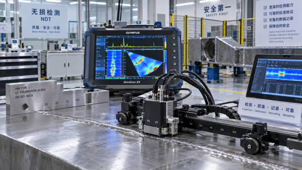
A specification becomes critical when an inspection team can detect an indication on one shift, yet another operator cannot reproduce it, or when a newly purchased instrument works well in the laboratory but struggles beside a hot weld, inside a confined vessel, or on a rough cast surface. In these situations, the problem is rarely the equipment model alone. The specification may have described a method without defining the inspection task, the required sensitivity, the reporting evidence, or the working conditions.
So, what should be included in a non-destructive testing equipment specification? At minimum, it should define the component and defect risks, the selected NDT method, measurable detection capability, calibration and verification rules, data requirements, environmental limits, operator workflow, safety obligations, and acceptance criteria. A useful specification does not simply request “an ultrasonic unit” or “an industrial radiography system”; it states what the system must prove, under which conditions, and how that proof will be recorded.
Start with the inspection decision, not the instrument category
Procurement documents often begin with a product label: phased-array ultrasonic testing, magnetic particle inspection, eddy current testing, computed tomography, or radiography. That is understandable, but it can lock a project into an unsuitable method before the inspection need is properly described.
The opening section should identify the item being examined and the decision that inspection must support. Relevant details include material type, product form, dimensions, access restrictions, surface condition, expected defect mechanisms, and the point in manufacture or service when the examination occurs. A weld inspection before coating, for example, has different access and surface-preparation requirements from corrosion mapping through a protective layer or in-service crack screening on a complex geometry.
Describe the defect concern in practical terms. Is the task intended to find planar cracking, volumetric porosity, lack of fusion, wall loss, delamination, inclusions, or dimensional variation? The answer influences method selection, probe design, scan coverage, image quality, and the type of evidence retained. “Detect internal defects” is too broad to be testable. A better requirement identifies the relevant defect orientation, inspection zone, and reporting threshold.
- Component identification, drawings, geometry, and accessible inspection areas
- Material grade or material family, heat-treatment condition, and surface finish
- Manufacturing stage or in-service condition
- Likely flaw types and locations of concern
- Required inspection coverage, including exclusions that cannot be accessed
- The action triggered by a reportable indication: accept, repair, monitor, or investigate
This context prevents an NDT system from being specified only by headline capability. A high-resolution method may not be the best production choice if it cannot inspect the required area at the required rate, while a fast screening method may be insufficient where sizing and permanent evidence are needed.
Define detection capability in measurable language
Detection sensitivity is often the most important part of the specification and one of the most poorly expressed. Terms such as “high sensitivity,” “high resolution,” or “suitable for small defects” do not establish an acceptance basis. Sensitivity must be tied to the material, thickness range, defect type, scan direction, coupling condition, and inspection procedure.
Where appropriate, the specification should state the smallest relevant discontinuity or the minimum signal response that must be detected under representative conditions. For ultrasonic testing, this may include reference reflectors, signal-to-noise expectations, focal-law coverage, scan index, and amplitude recording levels. For radiographic methods, it may include penetrated thickness, image quality indicators, contrast requirements, geometric unsharpness limits, and image review conditions. In eddy current inspection, the target may involve crack response relative to lift-off, conductivity variation, coating thickness, and probe orientation.
The document should distinguish between detection, characterization, and sizing. Finding that an indication exists is not the same as determining its depth, length, orientation, or severity. A system capable of locating a response may still require a different probe, scan plan, software function, or confirmatory method before the response can support a repair decision.
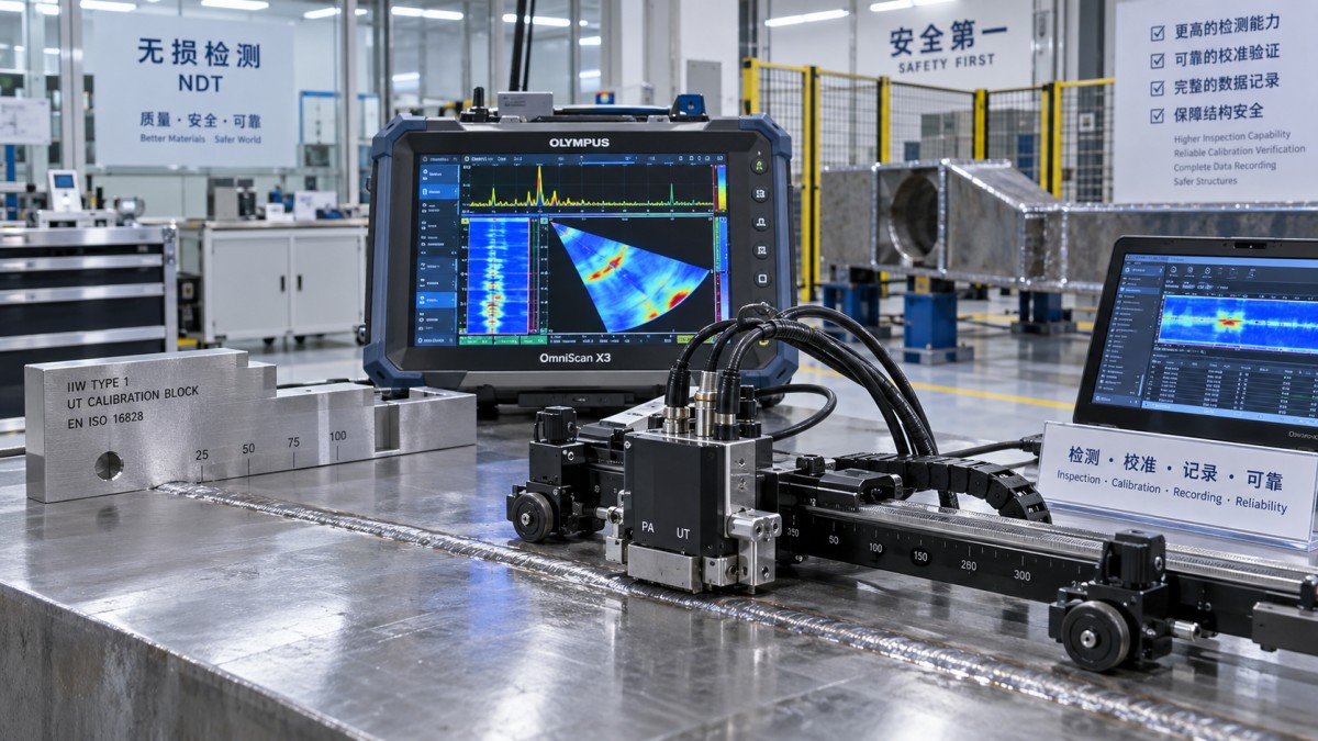
Match the NDT method to the inspection boundary
Comparison is useful only when it is built around the actual inspection boundary. No single method is universally superior. Each technique sees certain conditions well and has predictable blind spots that should be acknowledged in the equipment specification.
The specification should also state whether the equipment will be used as a primary acceptance method, a screening tool, or a secondary verification method. That distinction changes how much automation, traceability, redundancy, and reporting control are justified.
Do not separate equipment requirements from calibration
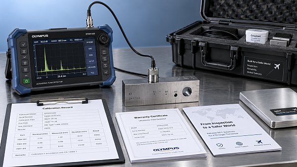
An NDT instrument is only as dependable as its verification process. A specification should require the equipment to support calibration and routine performance checks using suitable reference standards. It should define the standards needed, how they relate to the inspected material and geometry, what parameters are checked, and what happens when a check fails.
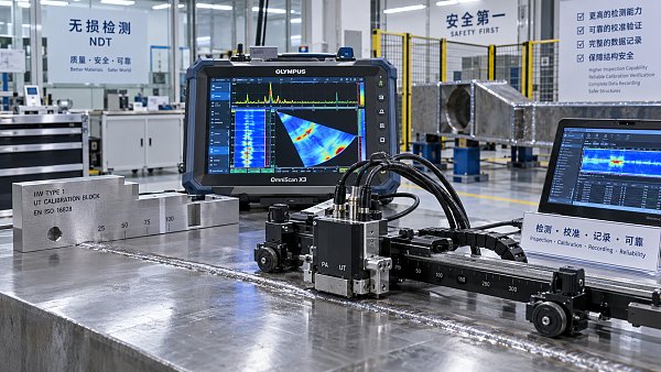
For a phased-array system, this may include element response, wedge delay, sensitivity equalization, encoder accuracy, and time-corrected gain validation. A radiographic system may require checks of detector performance, bad-pixel management, image quality, exposure repeatability, and monitor conditions used for image evaluation. Eddy current applications need reference samples that represent expected flaw signals and normal sources of variation, such as lift-off or geometry transitions.
There should be a clear distinction between periodic instrument calibration, pre-use functional verification, and procedure-specific setup confirmation. The first establishes traceability for relevant measurement functions. The second checks whether the equipment remains operational. The third confirms that the selected method is valid for the particular component and inspection plan. Treating these as one generic “calibration requirement” creates avoidable gaps.
Specify the evidence needed when performance drifts
Drift is not always obvious. A probe can wear, a cable can intermittently fail, an encoder can slip, detector response can change, or software settings can be altered by an operator. The equipment should be able to preserve setup files, calibration records, alarm messages, and relevant system status information. A failed verification should identify potentially affected inspection records and support a defined reinspection decision rather than leaving teams to reconstruct settings from memory.
Data capture and reporting need their own requirements
Modern NDT equipment can produce large amounts of data, but a specification should request useful evidence rather than every available file. Determine what must be retained for each examination: raw data, processed images, A-scans, C-scans, radiographic images, setup parameters, location coordinates, operator identification, calibration status, and review comments. The required retention format should be readable over the intended record life and protected against untracked changes.
Reporting requirements should state how indications are located and described. This may include component identification, datum references, weld or feature location, scan direction, depth estimate, signal level, evaluated dimensions, and disposition. Where automated defect recognition or software-assisted analysis is used, the specification should make clear that the output is an inspection aid unless the procedure establishes its decision role. The equipment should allow a reviewer to examine the underlying evidence, not only a final pass/fail label.
Integration may also matter. In a production cell, the system may need encoder inputs, part identification, barcode support, network transfer, industrial communication protocols, or interfaces with quality databases. These requirements should be defined early because they affect software architecture, data security, and commissioning scope. A portable unit used for occasional field examination may instead need simple offline export and robust local storage.
Write environmental and usability limits into the specification
An instrument that meets sensitivity requirements in a controlled room may fail to deliver repeatable results in its actual workplace. The specification should state operating temperature range, humidity, dust exposure, vibration, electromagnetic interference, lighting, noise, available power, and access restrictions. For outdoor work, screen visibility, weather protection, battery operation, and glove-friendly controls may matter more than an additional analysis feature.
Surface conditions deserve similar attention. Scale, paint, rough machining marks, curved surfaces, uneven couplant layers, and restricted probe placement can all affect inspection response. Rather than assuming ideal preparation, specify the allowable surface condition and identify any required preparation, coating removal, cleaning, or coupling medium.
Ergonomics and inspection rate also influence quality. A heavy portable unit, an awkward probe cable, or a scan system that is difficult to align may encourage shortcuts under production pressure. Relevant requirements may include instrument weight, probe reach, cable durability, scan speed, setup time, battery exchange, and the ability to pause and resume a documented inspection without losing positional information.
Acceptance criteria and standards must be connected, not merely named
A specification should identify the governing code, contractual procedure, internal quality rule, or engineering acceptance basis that applies to the inspection. Naming a standard alone is not enough, because the equipment requirement must reflect the particular method, component type, and acceptance level being used.
State who is responsible for defining acceptance criteria and who evaluates ambiguous indications. The equipment supplier may provide capability information, but acceptance limits are usually tied to the component design, service conditions, applicable procedure, and quality authority. The specification should prevent a common misunderstanding: instrument alarms, color maps, or automated classifications are not themselves acceptance criteria unless the approved inspection procedure explicitly makes them so.
A practical structure for the final specification
A complete document does not need to be unnecessarily long, but it should allow technical, quality, and purchasing teams to verify the same requirement. Organize the final specification around the following decisions:
- Inspection purpose: component, material, defect risk, coverage, and inspection stage.
- Method and capability: selected NDT technique, thickness or geometry range, required detection and sizing performance, known exclusions.
- Equipment configuration: instrument, probes or detectors, scanners, motion control, accessories, software, and consumables.
- Verification: calibration standards, routine checks, acceptable tolerances, and actions after failed checks.
- Records: required inspection data, report format, image or scan retention, traceability, and review access.
- Operating conditions: environmental limits, surface preparation, portability, power, access, safety, and workflow constraints.
- Acceptance and handover: demonstration on representative samples, documentation, training needs, maintenance information, and acceptance criteria.
The strongest NDT equipment specifications make uncertainty visible before a purchase order is issued. They identify what the method must detect, where it may be limited, how its performance will be checked, and what evidence must remain after the inspection is complete. That approach gives engineering teams a defensible basis for comparing systems that may appear similar in a product brochure but perform very differently in the actual inspection environment.
Questions about radar level measurement? Leave a message for application guidance from PIAS.
We respect your privacy. Your information is strictly confidential.
Related Intelligence
 Commercial InsightsNov 09, 2026Comparing Industrial Instrument Suppliers: Warranty Coverage and ExclusionsMake a smarter supplier comparison for industrial instruments warranty terms. Discover hidden exclusions, service costs, and key questions before you buy.
 Commercial InsightsNov 07, 2026Industrial Level Meter Costs: Purchase, Installation and MaintenanceCompare industrial level meters cost across purchase, installation, and maintenance. Learn how to evaluate lifecycle costs and choose the right meter.
 Commercial InsightsOct 27, 2026Optical Microscope Distributors in Europe: How to Verify Service and WarrantySearching for “optical microscopes distributor Europe”? Learn how to verify authorization, repair support and warranty terms to choose confidently and reduce costly downtime.
 Commercial InsightsOct 24, 2026Choosing an OEM Flow Meter Supplier: Calibration, Customization, and Lead TimesSource flow meters OEM teams can trust. Compare supplier calibration, customization, and lead times to reduce integration risks, control costs, and secure reliable supply.
 Commercial InsightsOct 19, 2026MDF Six-Sided Drilling Machines: Assessing Setup and Changeover NeedsExplore MDF six-sided drilling process details to assess setup, changeovers, tooling and connector fit. Discover practical checks to compare machines and make a confident purchase.
 Commercial InsightsOct 19, 2026Comparing Industrial Measurement Equipment Quotes: Hidden Costs to CheckCompare your industrial measurement equipment quotation with confidence. Uncover hidden calibration, software, and installation costs to avoid surprises and choose better value.
 Commercial InsightsOct 18, 2026EU Metrology Compliance: When Do MID and National Rules Apply?Navigate metrology regulation compliance Europe-wide: discover when MID or national rules apply, verify instrument approvals, and avoid costly deployment mistakes.
 Commercial InsightsOct 16, 2026Industry 4.0 in Southeast Asia: What Factory Data Should You Collect First?Explore Industry 4.0 data needs Southeast Asia factories should prioritize. Learn which machine, downtime, and quality data to collect first to reduce losses and guide smarter decisions.
 Commercial InsightsOct 15, 2026Dimensional Inspection System Prices: How Accuracy and Automation Affect CostCompare dimensional inspection systems price quotes to see how accuracy, automation, and ownership costs affect value. Learn what to ask suppliers before you invest.
 Commercial InsightsOct 13, 2026Choosing an NDT Equipment Exporter: Calibration, Warranty, and Import ChecksChoosing an NDT equipment exporter? Learn how to verify calibration, compare warranties, and check import requirements to avoid delays and buy with confidence.
 Commercial InsightsOct 09, 2026When do manufacturing inspection solutions reduce rework on production lines?Manufacturing inspection solutions reduce rework by detecting defects early, enabling faster corrective action, stronger traceability, and more efficient production lines.
 Commercial InsightsOct 09, 2026What Should Be Included in an NDT Equipment Specification?What should be included in a non-destructive testing equipment specification? Explore essential requirements for capability, calibration, data, safety, and compliance.
 Commercial InsightsOct 01, 2026Selecting Process Instrumentation Solutions for Chemical Plants: Measurement RisksProcess instrumentation solutions for chemical plants: identify measurement risks, improve reliability, and choose technologies that support safer, smarter operations.