How dimensional inspection metrology controls measurement uncertainty

A dimensional result is only useful when the team knows how much confidence to place in it. A part measured at 10.002 mm may appear compliant against a 10.000 +/- 0.005 mm specification, but that conclusion changes if the measurement uncertainty is large enough to overlap the tolerance limit. Dimensional inspection metrology controls this uncertainty by making the measurement process visible: instrument capability, calibration status, setup, environment, operator method, workpiece condition, and data treatment all become managed variables rather than hidden sources of doubt.
For quality and safety teams, this is not an academic distinction. Uncontrolled uncertainty can release parts that later fail assembly, leak under pressure, create excessive vibration, reduce fatigue life, or compromise a safety-critical fit. It can also reject conforming parts, driving unnecessary rework, supplier disputes, and production delays. The purpose of a metrology system is therefore not simply to produce a number. It is to support a defensible decision about conformance.
Measurement uncertainty begins before the instrument touches the part
A common mistake is to treat the accuracy stated on a caliper, coordinate measuring machine (CMM), optical system, or gauge datasheet as the uncertainty of every result produced by that device. That value may describe performance under defined conditions, using a prescribed artifact and a controlled method. The uncertainty attached to a production measurement is broader.
Consider a machined shaft measured for diameter. The final result can be influenced by probe force, gauge resolution, calibration uncertainty, thermal expansion, fixture alignment, surface finish, roundness, measurement location, cleaning condition, and the operator's interpretation of the datum. A shaft with a thin oil film or burr can produce a different indication from a clean, stabilized part even when the same instrument is used. On a large welded structure, part flexibility, local distortion, and datum accessibility may contribute more uncertainty than the measuring device itself.
Dimensional inspection metrology brings these contributors into a controlled measurement model. The model does not have to be unnecessarily complex for every feature. It does need to reflect the actual decision being made. A go/no-go thread gauge used to screen a mature, high-volume operation requires a different approach from a multisensor system verifying a tight profile tolerance on a prototype aerospace component.
Useful uncertainty control starts with four questions:
- What characteristic is being measured, and what functional risk does its tolerance protect against?
- What measurement method, datum scheme, and probing strategy will be used consistently?
- Which sources of variation could materially change the conformity decision?
- How will the inspection result be interpreted when it approaches a specification limit?
Without these answers, adding resolution or buying a more sophisticated instrument can create an appearance of precision without improving the reliability of the release decision.
The tolerance-to-uncertainty relationship determines whether inspection is credible
The first practical test is whether the measurement system is capable relative to the tolerance under review. There is no universal ratio that fits every part and risk level. A wide tolerance on a noncritical cover plate can tolerate more measurement uncertainty than the position of a locating feature that controls a braking, pressure-retaining, electrical, or flight-related assembly. What matters is that uncertainty leaves enough decision margin to distinguish acceptable and unacceptable product.
When the uncertainty interval is small relative to the tolerance zone, inspection can normally classify most results with confidence. As uncertainty grows, an increasingly large band near each specification limit becomes ambiguous. A measured value in that band may be reported as passing or failing only after the organization applies a defined acceptance rule.
This is where quality systems often become inconsistent. One inspector may accept any observed value within the drawing limit. Another may apply an internal buffer. A supplier may report a pass while the receiving site rejects the same part after considering its own method uncertainty. These disagreements are often described as gauge problems, but the deeper issue is that the parties have not aligned their decision rule.
International metrology practice addresses this through concepts such as measurement uncertainty, traceability, and guard banding. A guard band narrows the acceptance zone by an amount related to uncertainty when the risk of falsely accepting a nonconforming part must be limited. It can also be structured to control the opposite risk, falsely rejecting a conforming part. The correct policy depends on the consequence of an error, contractual requirements, regulatory obligations, and the function of the feature.
A safety-related sealing diameter, for example, may justify a conservative acceptance rule because an incorrect pass could lead to leakage or loss of containment. For a cosmetic dimension with a low functional consequence, a different balance may be commercially reasonable. The important point is that the decision rule must be established before marginal results arrive, documented in the inspection plan, and communicated across supplier and customer boundaries.

Calibration proves traceability, but it does not prove the whole measurement process
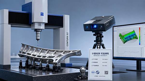
Calibration is essential because it links the instrument's indication to recognized standards through an unbroken chain of comparisons, each with stated uncertainty. For dimensional work, this may involve calibrated gauge blocks, setting rings, reference spheres, step gauges, artifacts, or certified master parts. A calibration certificate provides evidence that an instrument was evaluated under specified conditions at a particular time.
It does not automatically demonstrate that the instrument is suitable for every feature on every production part. A CMM can be calibrated and still give weak results if the stylus configuration is unsuitable, the program does not reflect functional datums, the fixture allows movement, or the part has not reached thermal equilibrium. Likewise, a handheld gauge may be well calibrated but inappropriate for a form error, deep internal feature, or datum-dependent position requirement.
Quality teams should separate three related but distinct controls:
- Traceability: The measurement reference can be connected to appropriate standards with documented uncertainty.
- Instrument performance: The equipment continues to operate within its defined specification through calibration, verification, maintenance, and environmental control.
- Method capability: The complete inspection process can produce repeatable and reproducible results for the characteristic and tolerance being controlled.
The third control is often the weak point. Measurement system analysis, including repeatability and reproducibility studies where appropriate, helps reveal whether different operators, setups, or measurement cycles produce materially different decisions. These studies should represent the real inspection condition. A study performed only on stable master artifacts may miss the surface texture, flexibility, orientation, access constraints, and feature-to-feature variation that complicate actual production parts.
Periodic verification with suitable check standards is also valuable between formal calibrations. It provides early warning of drift, damage, contamination, software changes, probe wear, or fixture degradation. The check standard must be relevant to the measurement range and mechanism. Passing a quick check near one end of a CMM's working volume does not establish performance for a large component measured across the full machine envelope.
Environment and part condition can dominate high-precision results
Temperature is one of the most underestimated uncertainty sources in dimensional inspection. Both the workpiece and the measurement system change size with temperature. A part transferred from machining, heat treatment, washing, or a warm shop floor may not have stabilized when it reaches inspection. Measuring it immediately can create apparent dimensional variation that is primarily thermal rather than manufacturing-related.
The risk rises with part length, material expansion characteristics, and tolerance tightness. It also rises when a controlled metrology room is assumed to solve the problem while the component itself is still carrying heat from the process. Recording room temperature alone is therefore insufficient for critical work. Teams need a practical procedure for stabilization, temperature monitoring, compensation where validated, and escalation when the part cannot be brought to the assumed reference condition.
Surface condition deserves similar attention. Coatings, burrs, oxide layers, contamination, machining marks, and compliant materials can all alter contact measurements. Non-contact optical systems avoid some contact-force effects, but introduce other sensitivities: surface reflectivity, edge contrast, lens calibration, lighting, focus, line-of-sight access, and algorithm settings. Switching from tactile to optical inspection is not a simple upgrade; it changes the uncertainty model and requires method validation.
For large fabricated assemblies, gravity-induced deflection and restraint condition can matter as much as temperature. The part may be inspected free-state, clamped in a fixture, or supported at defined points. Each condition can produce a valid but different result. The inspection setup should represent the functional condition specified by the drawing or engineering intent. Otherwise, a report can be technically precise while answering the wrong geometric question.
Data handling can either protect or weaken the conformance decision
Modern inspection software can collect dense point clouds, calculate geometric tolerances, apply alignments, and send results directly into quality records. That capability improves consistency only when the underlying measurement plan is controlled. An alignment choice can materially change the reported position or profile result. Filtering, outlier removal, sampling density, fitted-element method, and compensation settings can also affect the reported value.
For this reason, a controlled digital inspection process should retain more than the final pass/fail status. For critical characteristics, the record should identify the program revision, instrument or sensor configuration, reference artifacts, environmental assumptions, measurement strategy, operator or automated run identification, and applicable acceptance rule. This level of traceability is especially important when a nonconformance, field event, or supplier dispute must be investigated months later.
Automation reduces some human variation, but it does not eliminate uncertainty. Automated loading can change seating conditions. Robotic probing can introduce access or collision constraints. Vision systems can classify edges differently after a lighting or software update. Artificial intelligence-based feature recognition may accelerate interpretation, yet its output still needs validation against the tolerance, material condition, and defect modes that matter to the application. Automated inspection should be treated as a controlled production process, with monitoring and change management, rather than as a self-validating source of truth.
How to build an uncertainty-control plan that supports release decisions
An effective plan does not require every dimension to receive the same level of analysis. It should focus effort where poor measurement decisions carry the greatest consequence. Start by identifying the characteristics that control fit, containment, load path, clearance, safety function, interchangeability, or regulatory compliance. Then match the method to the feature, tolerance, production rate, material, environment, and required evidence.
For each critical characteristic, document the nominal value and tolerance, datum interpretation, equipment and fixture, calibration or verification requirement, measurement sequence, environmental condition, expected uncertainty, and decision rule near limits. Define what happens when an instrument check fails, a result falls inside the guard band, a part has not stabilized, or a measurement program changes. These response paths are more useful than a generic instruction to “reinspect” because they prevent improvised decisions under production pressure.
Standards and laboratory practices provide useful discipline here. The Guide to the Expression of Uncertainty in Measurement is widely used as a framework for evaluating and expressing uncertainty. ISO/IEC 17025 principles are relevant when laboratory competence and traceability are required. For coordinate measuring systems, applicable performance and verification standards can help define how equipment capability is demonstrated. Yet compliance with a standard does not remove the need to assess the actual part, method, and acceptance decision.
The strongest dimensional inspection programs make uncertainty visible at the moment a release decision is made. They do not wait for a complaint, failed assembly, or audit to discover that a reported value lacked sufficient confidence. When metrology is managed this way, inspection becomes a practical control on product and safety risk: the organization knows where its measurements are reliable, where the decision boundary is uncertain, and where the process needs a better method rather than a more optimistic result.
Questions about radar level measurement? Leave a message for application guidance from PIAS.
We respect your privacy. Your information is strictly confidential.
Related Intelligence
 3D Optical ProfilersNov 01, 2026Choosing High-Precision Non-Contact Measurement Systems for Surface InspectionCompare high precision non-contact measurement systems for surface inspection. Discover how to evaluate sensor methods, accuracy and real-world performance.
 3D Optical ProfilersOct 09, 2026How dimensional inspection metrology controls measurement uncertaintyDimensional inspection metrology controls measurement uncertainty through calibrated methods, environmental control, and clear acceptance rules for confident quality decisions.
 3D Optical ProfilersSep 20, 2026Non-Contact Measurement Resolution: What Limits Accuracy in Optical Inspection?Non-contact measurement resolution: discover how optics, lighting, calibration, motion, and contrast affect inspection accuracy—and learn practical ways to improve reliable results.
 3D Optical ProfilersSep 12, 2026Industrial Metrology for Aerospace: Inspecting Blades, Airframes, and ToolingIndustrial metrology applications aerospace manufacturers rely on for blades, airframes, and tooling—explore smarter inspection, NDT, traceability, and quality control.
 3D Optical ProfilersSep 10, 2026Surface Roughness Measurement: Choosing the Right Method for Machined PartsSurface roughness measurement guide for machined parts: compare stylus, optical, and 3D methods to improve inspection accuracy, reliability, and process control.
 3D Optical ProfilersAug 05, 2026How to Evaluate Portable 3D Optical Measurement Systems for On-Site InspectionPortable 3D optical measurement systems for on-site inspection: learn how to compare accuracy, speed, software, portability, and lifecycle cost before you buy.
 3D Optical ProfilersJul 27, 2026How to Choose a 3D Surface Profiling System for Precision Measurement Tasks3D surface profiling system selection starts with surface behavior, not specs. Learn how to compare methods, improve repeatability, and choose a system that fits real precision measurement needs.
 3D Optical ProfilersJul 17, 2026How to Choose Optical Metrology Systems in Germany for Precision InspectionOptical metrology systems Germany buyers trust should match accuracy, automation, and traceability needs. Learn how to compare suppliers and choose the right precision inspection solution.
 3D Optical ProfilersJul 15, 2026Nano-Level 3D Profiling Microscope: What Resolution, Scan Range, and Speed Really Matter?Nano-level 3D profiling microscope selection is not just about peak specs. Learn how resolution, scan range, and speed impact real defect detection, throughput, and quality decisions.
 3D Optical ProfilersJul 12, 2026How to Evaluate a 3D Optical Measurement Systems Manufacturer for Accuracy, Support, and ROI3D optical measurement systems manufacturer evaluation made practical: learn how to verify accuracy, compare support, assess integration, and calculate ROI before you buy.
 3D Optical ProfilersJul 10, 2026Optical Signals Analysis for Semiconductor Inspection: What Metrics Matter Most?Optical signals analysis for semiconductor inspection: discover the metrics that matter most—from SNR and contrast to spectral response—to reduce misses, control drift, and protect yield.
 3D Optical ProfilersJul 09, 2026How to Evaluate Surface Inspection Systems for ISO Compliance in Regulated ManufacturingSurface inspection systems ISO compliant evaluation starts with traceability, validation, and audit-ready data. Learn how to compare vendors, reduce compliance risk, and choose with confidence.
 3D Optical ProfilersJul 06, 2026Industrial Metrology Services for Aerospace: What to Verify Before Requesting a QuoteIndustrial metrology services for aerospace: learn what to verify before requesting a quote, from tolerances and traceability to reports, standards, cost drivers, and lead time.